PRODUCTION ITEMS
PRODUCTION
ITEMS
FLOW & LEVEL INSTRUMENTS
SYSTEM PACKAGE & MEASUREMENT ACCESSORIES
ORIFICE PLATE & FLANGES
Measuring Orifice
The orifice meter is a flat plate with a circular hole that has pressure taps up and downstream form the orifice plate.
There are in general four(4) methods of placing the taps. The coefficient of the meter depends upon the position of taps.
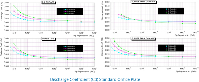
The discharge coefficient - Cd:This varies considerably with changes in area ratio and the Reynolds number.
A discharge coefficient, Cd-0.60 may be taken as standard, but the value varies noticeably at low values of the Reynolds number Pressure recovery of an orifice plate is very much limited and permanent pressure loss is primarily affected by the area ratio. For an area ratio of 0.5, the head loss is about 70-75% of the orifice differential.
Restriction Orifice
The restriction orifices are used ofr reducing fluid pressure are designed somewhat different form the orifice plates that are used for measuring flow rates.
There are some types of restriction orifice:
- Single plate with a single hole without bevelled 45º angle for pressure recovery.
- Multiple orifice(SMO-s). also know as Multi stage restriction orifice ofr high-pressure drops.
- Multi Hole type(SMO-H).
PREVENTS
- SMO-S : Cavitating and Flashing in liquid flows., Chocked flows in gases(some case in liquid flows).
- SMO-H : Exceesive Noise / vibration.
The bore edge of the restriction orifices may be survace-hardened by reinforcement with stellite(grade 6) or by nitriding on requesting.
Where very high pressure drops in liquid flows are required multiple type restriction orifice assmblies may be required to achieve the desired pressure drop while preventing problems such as cavitation, flashing and high noise and vibration levels.
also, where gas flows with very high pressure drops and required muti hole type restriction orifice for reducing high nose leves.
SOP-series
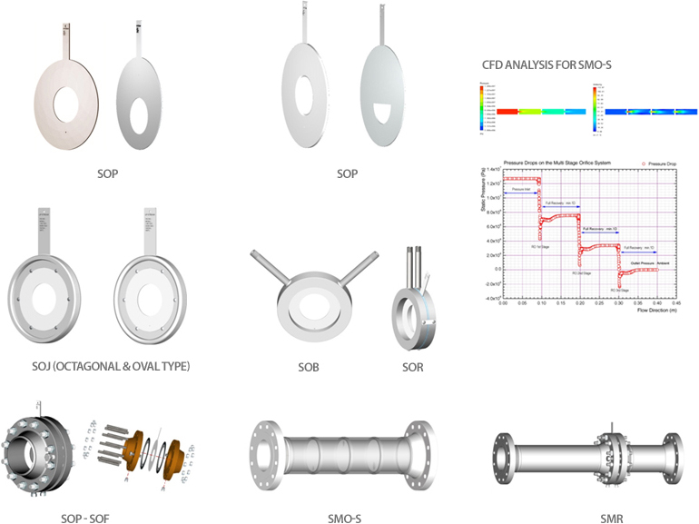
Measuring Orifice
- SOP
- SOR
- SOB
- SOJ
- SOP-SOF
- SIO
- SMR
Restriction Orifice
- SOP
- SMO-H
- SMO-S
- SRU
Standard Specifications
| Concentric | ISO 5167 (1991 & 2003) |
|---|---|
| ASME MFC-3M, 14M(for small bore) | |
| AGA Report No. 3 | |
| ISO/TR 15377 | |
| Eccentric | BS 1042, R.W Miller, L.K.SPINK |
| Segmental | R.W Miller, L.K.SPINK |
| Quadrant | BS 1042, R.W Miller, L.K.SPINK |
| Conical | BS 1042, R.W Miller, L.K.SPINK |
| Concentric | R.W Miller, L.K.SPINK |
|---|---|
| Rating | 150# ~2500# |
| Special Flange union design per ASME B&PV, VIII, Div.1 | |
| Material | Orifice Plate : Min. 316LSS |
| Flange union : per customer's MPS | |
| Calculations | Sizing calculation (will be submitted) |
| Noise prediction (can be submitted on request only) | |
| Thickness & Deflection (can be submittd on request only) | |
| Cavitating flowsc (can be submitted on request only) | |
| Accuracy | ±0.4 % (calibrated & extrapolated) |
| ±1 % to ±2%(uncalibrated) | |
| Rangeability | 5 : 1 for indication or recording |
| 3.5 : 1 for control application |
Options
- Nipple
- Tap valve
- Straightener (per ISO 5167, API 14.3 (AGA 3 part 2)
- Others are available on request